Session 5 provides an understanding of how to plan and design a network. It covers the concepts of how to structure a network to best needs of business and users.
Before buying the components of the network we first determine what we want to accomplish with the network. Questions to answer are:
- What applications will be running on the network. (Cloud Services, Remote Access, Video Streaming, VOIP , NAS, Gaming, IOT)
- How many users does the network need to support. (Capacity, Security)
- What is the layout of the premises and where do you want to have access to the Internet.
- Do you need network access outside the premises.
- How many devices do you need to connect wired. (Ethernet)
- How many devices will connect using wireless. (Wi-Fi , Bluetooth)
So taking these points into consideration, we need to plan for a network that is suitable for a 3 to 5 year period. A key point to remember is that an increasing number of devices require a connection to the Internet. Most of these new devices connect using wireless, so good wireless coverage and bandwidth is important .
Initial Setup
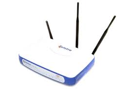
Initially the Internet Service Provider (ISP) will provide you with a modem/router with a switch and Wi-Fi built in as shown above. They can be described as Swiss Army knife style devices used in many small networks. They are usually cheap generic boxes with limited capabilities as listed:
- Designed to connect to 4 wired devices by the internal switch
- Limited Wi-Fi range usually with 15 metres.
- Basic security functions with no Quality of service capability
- No Virtual Private Network (VPN) support
- Limited CPU capacity and data throughput
- No expansion capability
The ISP supplied devices are designed for the purpose of getting a small number of users and devices connected to the Internet both wired and wireless from the network.
As the needs of the network increase requiring more data and devices to be connected the multipurpose ISP supplied box will just slow down and create a bottleneck on the network.
So with these limitations in mind the best way forward to plan and build the network for increased capacity and expansion is to look at the functions required and separate the devices into a modular design.
Network Router
Once the planning questions have been answered the first network component to look at is the router. This is important because the router is the point to the outside world and all data will pass through this device.
A good dedicated router should have the following:
- Easy to manage using web interface
- Speed the amount of data packets per second it can process, the throughput
- Supports Quality of service meaning so we can prioritize streaming media, gaming and web browsing
- Integrates easily into the network design
- Has the ability to scale with the network needs.
- Good support by manufacturer
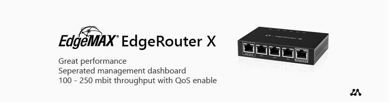
The EdgeMax router shown below is an example of a cost effective router with all the required functions mentioned. It is well supported and works as part of an integrated family.
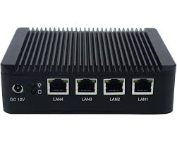
Another popular router is pfense. Initially developed as a open source firewall software application it can be installed on generic hardware to build a cost effective router with built in high end security. The image below is a typical example of a pfsense router seen in a medium size network.
Network Switch
The next component in the design to consider is the switch. The switch will determine the throughput on in the internal part of the network known as the Local Area Network (LAN).
When selecting a switch some of the functions to consider are:
- Number of ports required for the Ethernet wired devices
- Speed of switch ports. (Gigabit Ethernet and above)
- Do the switch ports have to be Power over Ethernet (PoE)
- Does the switch support Virtual LAN (VLAN) tagging
- How will the switch be managed.
- Physical size of the switch and where can it be located
The first main criteria is that the switch should have enough ports to accommodate the hardwired devices such as computers, NAS servers, printers, Smart TV and possibly video cameras. Remember to allow for extra ports for expansion.
In the case of video cameras they typically will be located at various points around a premises so if they are hard wired they will require a PoE port from the switch to provide power.
As the network is now starting to become more complex it is best to segment traffic across the switch to reduce conjestion. This is where the VLAN tagging will be needed to ensure efficient transmission of data.
Again a simple web based management interface is desirable for controlling and monitoring the switch performance. The switch should have enough built in capacity to handle the load of the network for the 3 to 5 year period.
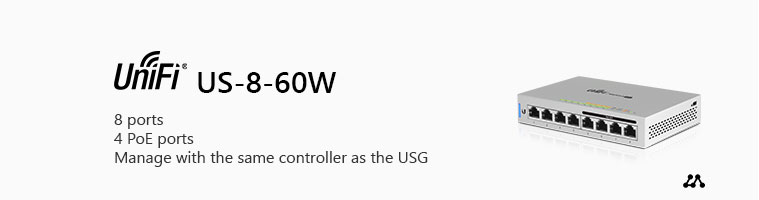
The Unifi switch shown below is an example of a cost effective switch with all the required functions mentioned. It has both normal gigabit ethernet ports and POE ports for flexibility as well as VLAN capability. It is well supported and works as part of an integrated family.
Wireless Access Points
A router in an network is never placed in the optimal position for good wireless coverage. It typically is located next to the Internet connection point on the premises. This is one reason why modem/router boxes with inbuilt wireless networking are not good at providing Wi-Fi coverage.
With the increased demand for mobile device connectivity the wireless coverage and speed has become the most important part of a good network design. To meet the demands of wireless networking correctly located dedicated Wireless Access Points (WAPs) must be installed.
The image below shows a typical WAP centrally located on the ceiling in a room providing all-round Wi-Fi coverage.
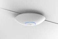
Typically in large floor plan areas it is wise to install multiple WAPs with overlapping coverage areas to ensure seamless connectivity as the connected mobile devices move around the premises.
Network planning and design is an ongoing process. If good design principles are adhered to at the beginning the network will be able to scale and adapt as required. The problem comes when a network is built in an ad hoc manner with little thought for the desired outcome. So it is wise to sit down and map your requirements before adding extra components along the way.
There are many tools to help you with the design process but it is wise to research and discuss your ideas with experienced users.
Here is a link to the Unifi network planner which can be used as starting point of the design.
Practical Activity
Using the diagram below build the following network
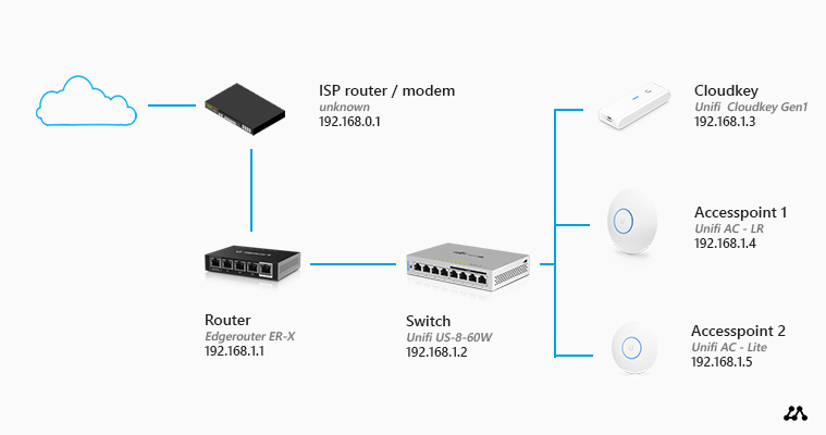
- Router
- Connect a computer to the eth0 port on the router
- Set the Computer IP address to 192.168.1.2 /24
- Using the admin account and Web Browser login to the router using IP 192.168.1.1
- Configure the WAN port (eth0) for connection to the Internet .
- Confgure the LAN network for the 192.168.10.0 network
- Set the DHCP pool for the LAN
- Ensure eth1, eth2 , eth3 and eth4 ports are set for the LAN network
- Set eth4 for Power of Ethernet (PoE)
- Switch
- Connect the switch to the eth1 port on the router
- Connect the computer to a port on the switch
- Set the computer for DHCP address
- Run the ipconfig command to confirm computer IP address is on 192.168.10.0 network
- Ping the LAN IP address 192.168.10.1
- Ping the WAN IP address
- Connect the Cloudkey controller to a switch port .
- Connect the wireless access point (WAP) to a switch port
- Cloudkey controller
- Identify the IP address of the cloud controller
- Login to the controller using a web browser and admin account
- When logged in identify the WAP
- Set the WAP IP Address to static 192.168.10.100 /24
- Set the access point SSID and WPA2 security with a key.
- Connectivity
- Using a mobile device connect to the network using the WPA2 security key.
- Using the ping command confirm the connectivity to switch and router.
- Open web browser on the mobile device and connect to the Internet.