As mentioned previously fixed wireless networks a typically used in situations where older cable connections are providing poor service or fibre links are not viable.
The fixed wireless topology has the advantage of being relatively easy to setup with ability to scale in speed and capacity.
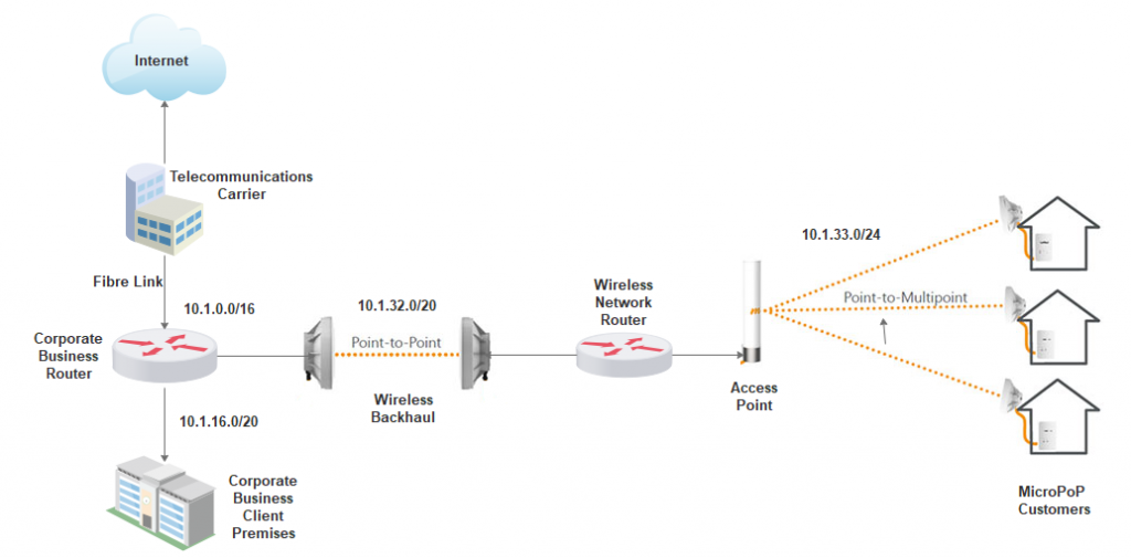
The diagram below is an example basic topology of how to connect a fixed wireless network to a fibre backbone. In this example the Internet fibre connection from the Telecommunications Carrier has already been installed to a business client via the Corporate Business Router. Using the wireless back haul point to point link the Wireless Network Router is able to provide an Internet connection to the access point and onto the MicroPoP customers.
Topology Main Points
- The wireless network takes advantage of an existing Telecommunications Carrier (Telco) fibre link. This reduces the startup infrastructure cost for the MicroPOP and provides another revenue stream for the Telco.
- The wireless backhaul would be located on top of the Business Client Premises to provide better line of sight connection for the Point to Point link
- The wireless network is segmented from the corporate network via the Wireless Network Router. This provides packet broadcast domain separation for the MicroPoP as well as network security for Coporate Business network. Also behind the Corporate Business Router there would be a firewall providing strict access rule sets.
- The network is using private IPv4 addressing. The 10.0.0.0 network address is used as it provides flexibility for network growth.
- The network uses variable length subnetting (CIDR notation) to allow for scalability for the network and clients.
Points for Improvement.
- To provide total physical separation from the Corporate Business network the Telco could utilise a separate fibre pair in the existing cable combined with another router to connect to the Wireless Network. In many situations this is standard practice.
- To allow better scalability a Virtual LAN (VLAN) capable switch could be included behind the Wireless Network Router to increase the number of MicroPoPs.
- Adding further interconnected back haul links at different locations to create a mesh network. This will provide better redundancy and failover into the wireless network.
- The private addressing scheme illustrated may not used by the Telco as this may cause a double NAT situation which can introduce performance issues in the network.
Notes
This topology may not be the best practice for your situation. It provides only an insight on how to connect a wireless MicroPoP to a Telco using easily available resources.
It is important that you use this information as starting point for your own design. The best solutions usually come from many discussions and viewpoints.