How to build an automated irrigation system for your garden.
In this article I have documented the process of designing and constructing a simple automated water irrigation system than can be expanded and adapted as required. The article is meant to be an overview so it is easy to follow.
I would be happy to provide more in-depth information. So I encourage you to provide comments on what things interest you.
Generally most commercial off the shelf irrigation systems available in the market are proprietary in their hardware and software. They provide minimal flexibility. This means the customer is locked into limiting technologies and applications.
With this in mind here are my requirements for designing this automated irrigation system:
- Easy to build and cost effective
- Flexible and can be customised
- Hardware and software are open sourced and well supported.
- Easily expanded and adapted to meet future requirements.
- Can be monitored and controlled from anywhere using existing Internet router.
- Has the ability to run on a stand alone sustainable power supply
Diagram 1 is the automated irrigation system incorporating the above mentioned requirements.
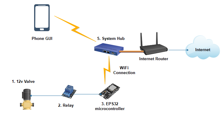
Diagram1. (Automated Irrigation System)
The design of the system was kept simple at this stage with the goal of being easily installed and maintainable. It is a proof of concept that can be scaled and changed depending on your needs and desires. As it stands the system provides an automated irrigation function with the ability for manual control via a computer or mobile phone.
The system can run as a standalone network or be incorporated to an existing WiFi LAN via cable connection to an Internet router. By connecting the hub station to your router you can also add secure remote access the irrigation system via the Internet. This is a very desirable function especially when you are travelling.
All hardware components for this system were sourced online and the controller software is open sourced.
System Hardware parts breakdown.
Diagram 2 is the controller system for the irrigation system. The individual parts are labelled and a described below.
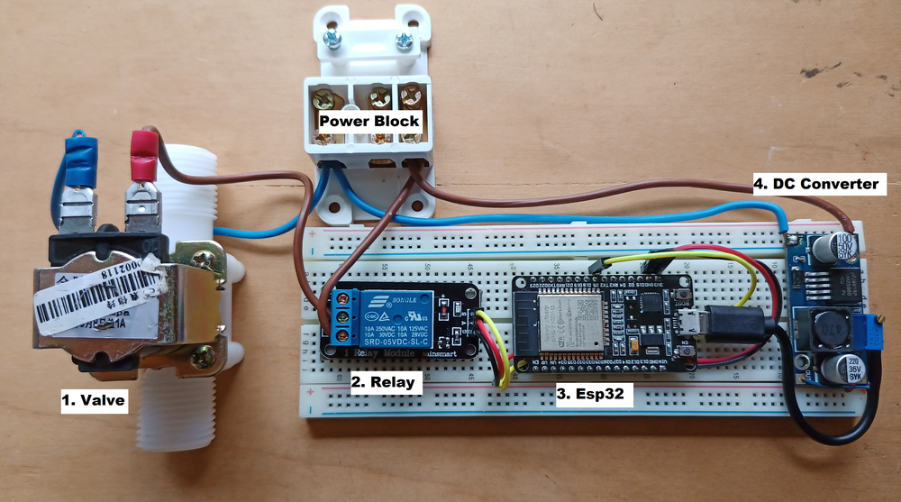
Diagram 2 (Irrigation system controller)
The control system is powered by 12V power supply. In this case I am using a spare 12 volt adaptor I had available. You could easily replace the adaptor with a rechargable battery attached to a small solar array. This would make system more self sufficient.
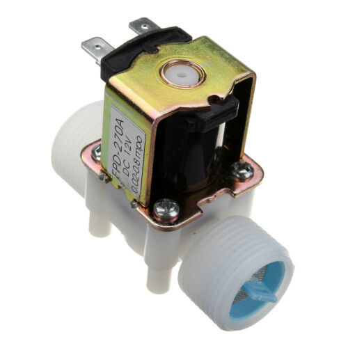
1. The 12v valve that controls the water flow from the tank to the irrigation pipes in the garden. This is a generic inexpensive part purchased on Ebay.
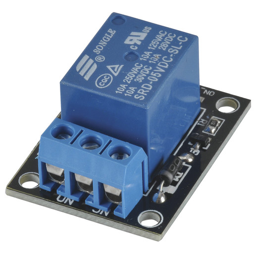
2. The relay that controls power to the water control valve. It is a common low cost relay that can switch both (30 V) 10 Amp DC and (120 -240V) 10 Amp AC devices.
3. The ESP 32 micro-controller. The ESP32 has a dual microprocessor with built in WiFi and Bluetooth. It has 34 General Purpose Input Outputs (GPIO) so it can control electric gates, pumps and motors. It also has the ability to measure climate attributes such as temperature, humidity, water level and soil condition with added sensors. In this build I am using only one GPIO to control the irrigation valve.
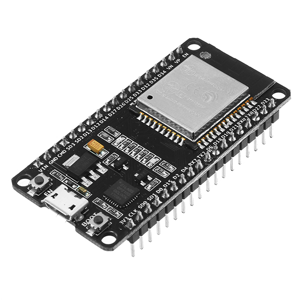
The ESP32 micro-controller provides the bidirectional WiFi communications with the system hub shown in Diagram 3.
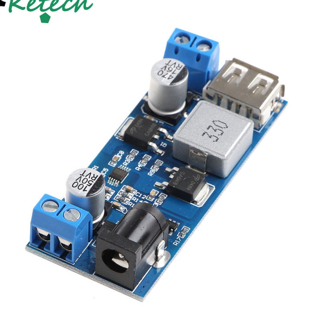
4. The DC voltage converter. This steps down the 12voltage supply to 5V to power the ESP32 micro-controller. The 12v supply also powers the valve to open close the water supply.
5. The system hub. The hub is a Raspberry Pi single board computer. It is running a software program called Home Assistant.
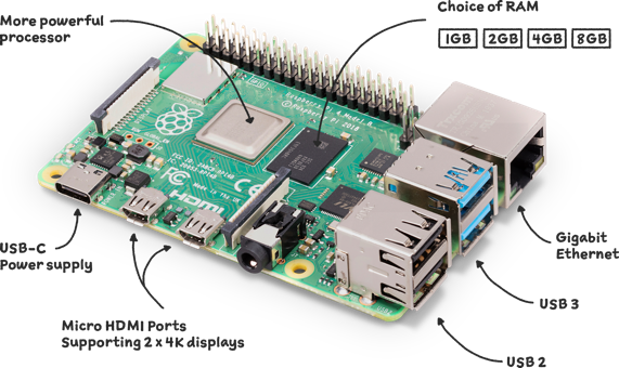
The Raspberry Pi is basically the server in the irrigation system as it contains all the automations and provides manual control for the users via it’s custom web pages. All control is done locally so no external cloud connections are required. In this design the irrigation system the hub is connected to the home Internet router using an Ethernet cable to provide secure remote access for external monitoring and control.
Diagram 3. shows the system hub connected to a Telstra Internet router using an Ethernet cable to a LAN port.
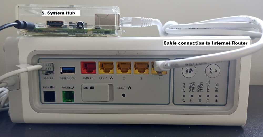
Diagram 3 (Irrigation System Hub connected to Internet Router)
System Software Overview.
The Hub runs Home Assistant. It is a very popular Open Source software product for automation used by thousands of applications across the world. I chose Home Assistant as it is free to use and has wide community and industry support. Diagram 4 is the graphical front end of Home Assistant.
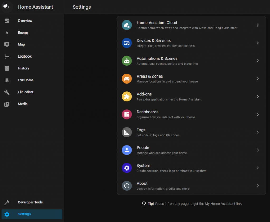
Diagram 4 (Home Assistant Configuration Page)
In this system I am only using a couple of basic automation scripts to control the turning on and off of the water valve at specified intervals. The following Diagram 5. is a screen shot of the Watering Garden on automation.
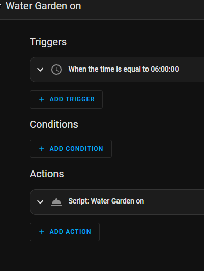
Diagram 5 ( Irrigation Automation)
The automation is triggered to activate when the time is 6.00 am every morning. The valve is open for 20 minutes then the water is turned off.
I have not set any conditions for this automation at the moment. You could add a condition such as do not turn on the water if a connected rain gauge monitor is over 50 % full. The conditions are endless and dependant on how you set up and program the system.
The last attribute is the action which is the call the script to turn water the garden.
User interface
The hub provides control and feedback via it’s build in Graphical User Interface (GUI). Diagram 6. shows the current GUI on the phone. It is totally customisable to what is presented to the user. In this Diagram I have created a Water Garden button at the top of the screen to provide manual switching of the irrigation system. The middle is the watering history automation showing when the watering was operating by Home Assistant. The bottom is a real time 5 day weather forecast imported into the program. The display options are up to you. They are only limited by the screen size and your attributes you setup in Home Assistant.
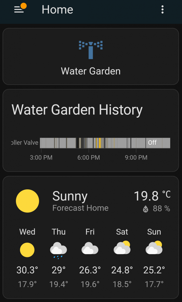
Diagram 6 (The GUI shown on the phone)
As mentioned this irrigation system is at the base level. It will develop as the needs and applications evolve.
I encourage you to comment on this article and provide feedback.
Thanks for reading.
You can contact me at my website Lupetec.com
Regards
Tony Duffy